Hardware Installation Guide
This document outlines the process of planning and installing the physical Cascade-500 IoT Gateway hardware. It lays out common planning questions to be considered, recommendations from Rigado, and the physical mounting and installation process. Please read through the entire document prior to beginning installation of hardware.
Click here to access our Resource Library & Product Documentation PDF's on our website.
Planning
Planning is key to the success of any hardware installation. There are many things to consider when installing a wireless system into a space. Key elements for consideration are listed in the sections below.
Coverage
In a typical commercial space, each gateway covers an area of approximately 4,000 sq. ft. However, the area of coverage for each gateway is dependent on the layout and construction of the facility where it is installed. A gateway in an open floor plan will have a larger coverage area than a closed floor plan with many walls. Building construction materials also affect coverage: drywall and glass permit more coverage than brick and concrete.
Coverage planning should consider brick or concrete walls, as you should not expect to get much penetration through those materials. If you require coverage on both sides of a brick or concrete wall, plan for a gateway on each side.
If a higher level of coverage planning precision is required, Rigado suggests using a Wi-Fi site planning tool to simulate coverage. There are multiple planning tools available online, both free and professional. For use in this application the tool should allow for changing the characteristics of the Access Points to match those of the Cascade-500 IoT Gateway (these specs are available from Rigado upon request).
Placement
Correct placement of Gateways is important for getting the desired coverage. Generally, mounting gateways up high and out of reach is recommended, as this improves line of sight while making the units more difficult to tamper with. Special consideration should be given to any metal near the mounting area, such as in support beams or HVAC ducts.
Rigado recommends against mounting the gateway directly to any large metal surface.
Gateways do not need to be visible for operation. It is common to mount Gateways above drop ceilings, to either the wall or a drop from the ceiling. When mounting above drop ceilings or in open office style spaces, it is recommended to mount the Gateway below the level of any ceiling HVAC ducts to avoid dead spots.
When determining mounting locations, nearby wireless appliances should be considered as well. Gateways should be separated from other 2.4GHz emitters like Wifi access points by at least five feet. Operating in close proximity to other radio equipment may degrade the reception and performance of both devices and could lead to damage of the appliances.
Wall Placement Guidelines
- Mount with the face towards coverage area
- Mount high and out of reach/active work area to avoid damage
- Mount above tallest obstructions
- Mount away from corners to maximize coverage
- Mount away from shelves, cabinets, HVAC ducts, and other obstacles
- Mount away from WiFi Access Points or radio equipment
- Goal is to maximize line of sight to coverage area
Ceiling Placement Guidelines
- Mount on lowest available mounting point facing downwards
- Mount below I-beams or support beams
- Mount away from HVAC ducts
- Mount away from WiFi Access Points or radio equipment
- Maintain clear line of sight or minimize obstacles to desired coverage areas
Gateway Power
The types of connections required should be taken into consideration when planning a new installation. In order to function, the Gateway needs both a power and Internet connection. For power, the options are PoE (Power-over-Ethernet) or AC wall power (adapters available upon request).
Rigado suggests using PoE-enabled Ethernet for gateway connection. PoE connections allow for both data and power to be provided to the Gateway, requiring only one cable for installation.
Wireless Network Connections
Special consideration needs to be given when choosing to use Wi-Fi, as the Gateway is always connected and does not have a physical user interface.
If using WiFi or Cellular for Gateway network backhaul, the strength of the network connection should be verified as part of the installation process. Poor network connectivity strength can result in unstable network connections and latent Gateway networking failures. Network coverage can degrade at any point due to network load from other devices, moving of large RF shielding objects like cabinets or racks, and even access point or tower failures, all of which can result in temporary or permanent network degradation.
For installation verification, Rigado recommends each interface be in Excellent or Good condition:
| Signal Quality | WiFi Max RSSI | WiFi Min RSSI | Cell Max RSSI | Cell Min RSSI |
|---|---|---|---|---|
| Excellent | - | -67dBm | - | -65dBm |
| Good | -68dBm | -80dBm | -66dBm | -81dBm |
| Fair | -81dBm | -90dBm | -82dBm | -96dBm |
| Poor | -91dBm | - | -97dBm | - |
Gateway network health and signal strength reporting can be found in Edge Direct under the Gateway Network tab for each Gateway.
Rigado Recommends all Wireless Network Interfaces to have Excellent or Good signal strength for reliable connectivity. Using network connections with lower signal quality may result in unstable connections or loss of data.
For WiFi, some corporate IT policies require updating passwords after a set number of days, which would break a Gateway's WiFi connection and require manual configuration on each Gateway to update the password. Before installation with on-site IT, please verify that the WiFi network being connected can retain the same credentials for Gateways.
Cellular connectivity is an option to work around network limitations or lack of network coverage. When using cellular, there are multiple considerations and steps that must be taken before a Gateway will connect to a network:
- A cell carrier with a monthly data plan must be established
- An active SIM card (3FF form factor) must be inserted into the Gateway
- The Cell carrier APN must be configured via Edge Direct and pushed to the Gateway via an active network connection.
For more details on using Cellular, please see Cellular Connectivity.
Pre-Site Planning Checklist
Summary of useful considerations when planning a gateway installation:
- Site location
- Area of where the sensors will be installed
- Available power outlets and height/distance from coverage area
- Is there a tall ceiling or obstructions to plan for?
- Is the area protected from the elements and/or temperature controlled?
- Are the Site network configurations set and applied to all Gateways?
- Check Wi-Fi or cellular signal strength in the proposed coverage area
- Decide gateway count and mounting location
Gateway Hardware
Power Supply
Power can be delivered through the barrel jack or through PoE. Power through the barrel jack (5.5mm x 2.1mm) should be 5V DC, 2A. The optional DC power adapter has a 5 ft. cable length and is certified for use with Cascade-500 gateways.
PoE can be delivered via the Ethernet connector (RJ-45) with IEEE 802.3af compliant PoE injector or switch (midspan or endspan).
Standard operating temperature is 0 to +60°C. Extended operating range is -20 to +70°C (operating over the extended range may result in reduced performance).
Interfaces (Cascade-500 and Cascade-500-W)
Interface features are described throughout this section, including power and data connectivity, and button and LED location and behavior.
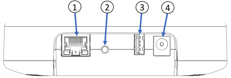
1. Ethernet with Power-over-Ethernet Support
The gateway is equipped with a single 10/100 Base-T Ethernet connector. For configurations supporting PoE (802.3af), the gateway will operate when powered by either a PoE switch (endspan) or injector (midspan).
2. Reset Button
The reset button provides both soft and hard reboot capabilities, depending on the length of the press. The timing is described in the following table:
Reset Action Time Behavior
| Reset Action | Time | Behavior | Unit LED Behavior |
|---|---|---|---|
| Quick Press | < 2 seconds | Soft Reboot | No LED state change |
| Short Press | 2-4 seconds | Network Reset | LED blinks fast Yellow, blinks fast Green on release |
| Long Press | 10-15 seconds | Hard Reboot | LED goes solid Yellow, LED goes dark after release |
| Very Long Press | > 30 second | Factory Reset | LED goes solid Yellow, then Black, release after LED goes back to solid Yellow |
Gateways can only be Factory & Network Reset or Soft Reboot after the unit has finished initial boot. The Gateway LED will blink fast yellow or solid green to indicate it is booted.
A Soft Reboot will restart the operating system on the gateway without interrupting power.
Network Reset clears all connections configured by Network Configuration and requires the button to be pressed for 2 to 4 seconds. To aid timing for Network Reset, the LED quickly flashes yellow to indicate the window when the button should be released. When the button is released during that window, the LED will quickly flash green to confirm the Network Reset operation has been triggered. If released after 4 seconds, the LED will return to the behavior it displayed before quickly flashing yellow. If the button is released between 4 and 8 seconds, no actions (Reboot or Reset) are performed.
Network settings are retained through a Factory Reset. This enables a device that was configured for Wi-Fi to regain network access after a Factory Reset is performed. To clear network settings, perform a separate Network Reset.
A Hard Reboot will force a reset of the processor and restart the operating system.
Factory Reset should not be performed unless instructed to by Rigado Support staff. Factory Reset will wipe all data from the gateway and re-install the factory default operating system image. If the gateway loses power during the re-install process, the installation might be corrupted, and the gateway rendered inoperable. If performing a Factory Reset, do not remove power while the LED is solid yellow.
Factory Reset on Cascade 500 series Gateways takes between 45-60 minutes to complete. Gateway LED indicator will be solid yellow throughout this process.
3. USB
A USB 2.0 Type-A connector on the gateway board provides access to a High Speed (up to 480Mbps) USB host.
For security, the USB port will not automatically recognize standard USB devices. Rigado must implement authorization on the gateway to allow USB devices to be recognized and applications on the gateway are not given access to the USB interface.
4. Barrel Jack
The gateway provides a 5.5mm x 2.1mm barrel jack for 5V DC input. Any AC/DC wall adapter used to power the gateway needs to be rated up to 2A and certified for use in the region of installation.
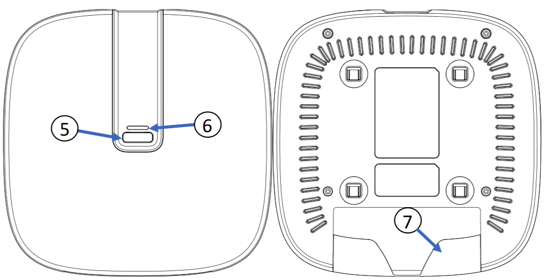
Front and Back faces of the gateway
5. Front Button
A button is located on the front face of the gateway. This button is not enabled on the default gateway configuration.
6. Multi-color LED
A multi-color (red/yellow/green) LED located near the user button provides a means of visual indication for the user. For additional information regarding LED behavior, please refer to
Gateway Boot Status
7. Cable Cover
The rear of the unit has a snap-in cover for improved cable management. This allows for hidden cable routing when the unit is installed on a wall or ceiling. The cable cover is removable.
Additional Interfaces for the Cascade-500-W
The Cascade-500-W IoT Gateway with cellular has more physical features than its non-cellular counterpart.
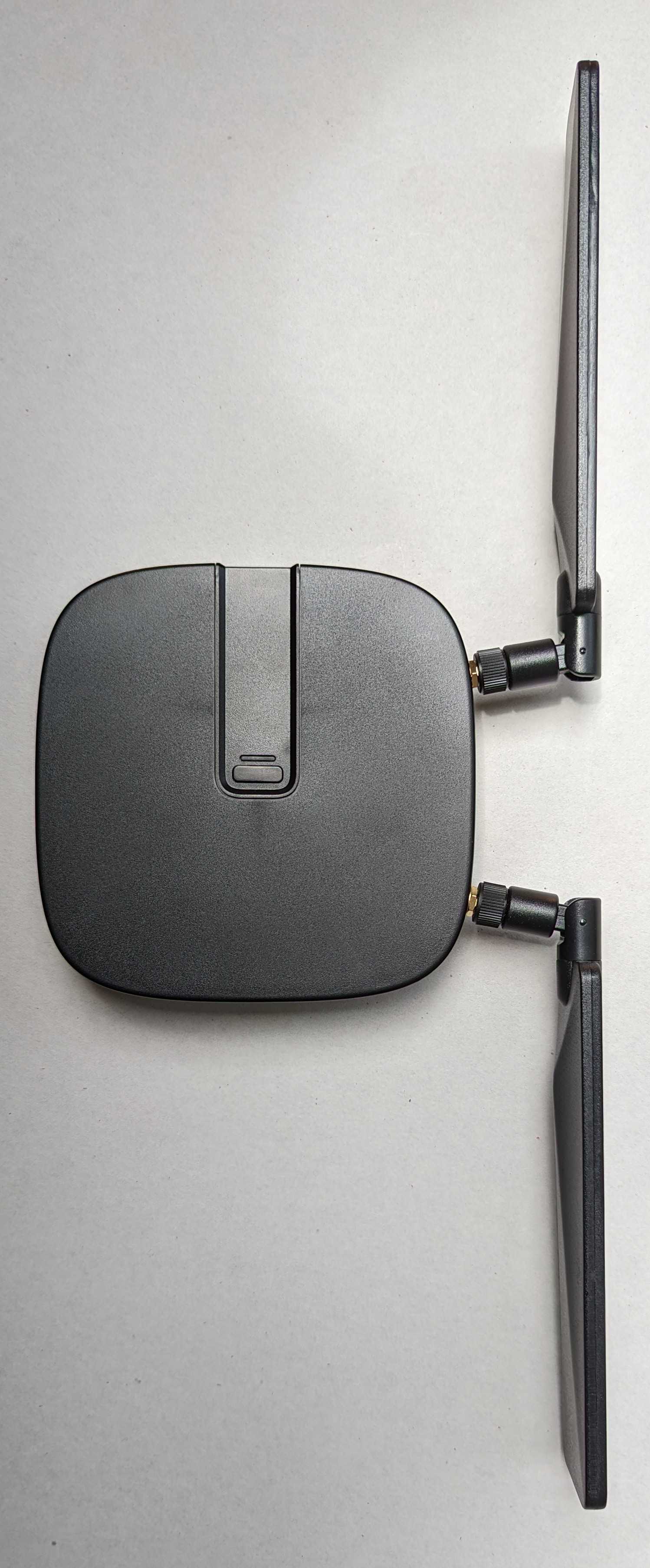
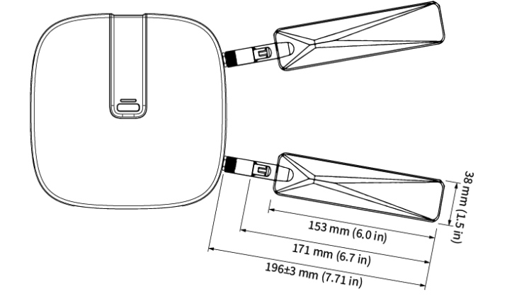
C500W Gateway Antenna & Orientation
The cell antennas should be approximate. Vertical for best results; the pattern is like a donut sitting around each antenna. Minimum recommended clearance between antennas and any RF blocking material (metal or concrete) is 6 inches. If mounting near/against these surfaces it is recommended that antennas be oriented perpendicular to the obstructions.
Standard Horizontal / Ceiling Mount
Antennas mostly vertical, a slight angle out is recommended. (Trades a bit of vertical orientation for increased distance between antennas)
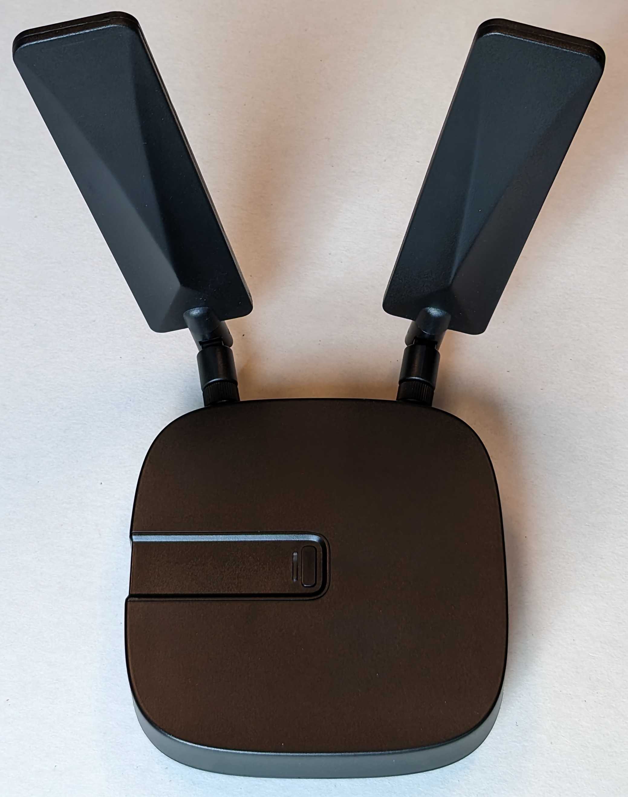
Cascade-500-W Gateway, Standard Horizontal/Ceiling Mount
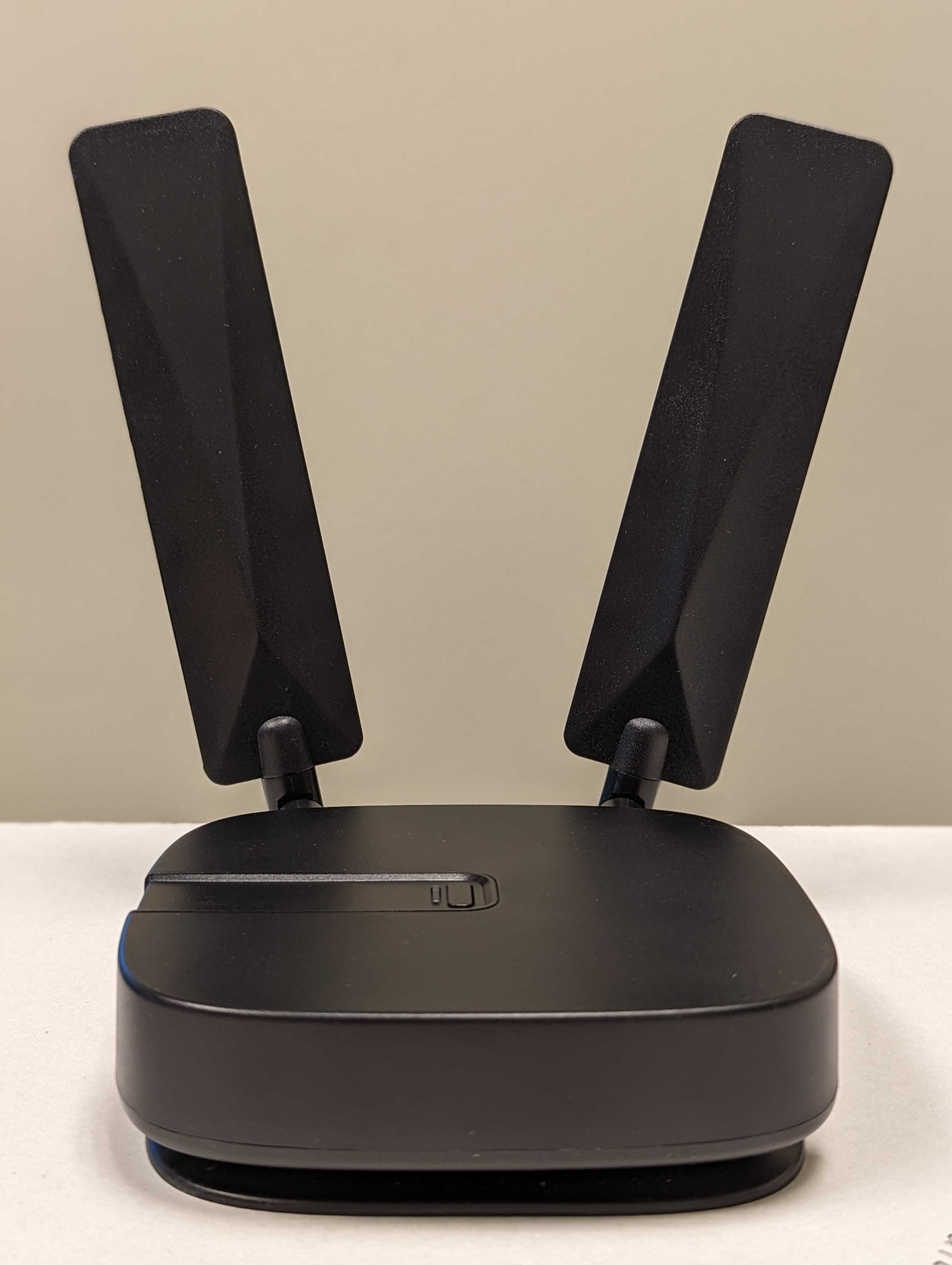
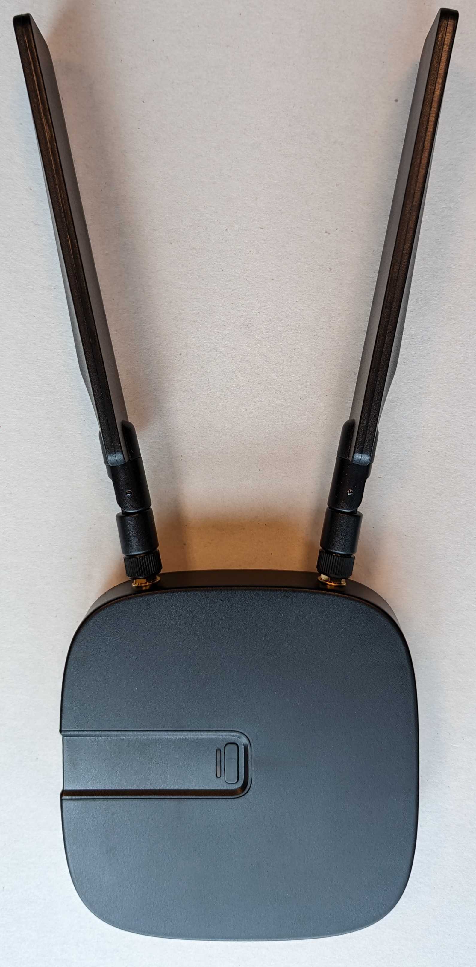
Vertical / Wall Mount
Note the decal tab is facing up. This is required for EN/IEC 62368 safety due to the mounting plate hook design. In any other orientation, the gateway could be detached with sideways or downward force.
Cascade-500-W Gateway, Vertical - Wall Mount
Additional Option
If the unit is wall mounted in an enclosure or secured where it can’t be inadvertently bumped – Position the antennas straight out. This orientation is better for the Bluetooth radio.
Cascade-500-W Gateway, Best Bluetooth Orientation
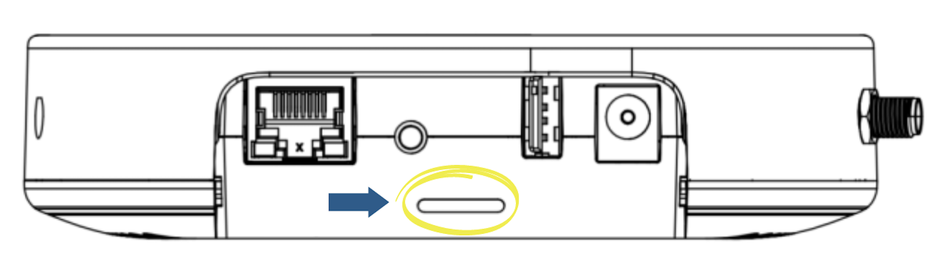
1. SIM Card Slot
The rear face of the Cascade-500-W includes a small narrow slot to insert a SIM card for cellular connectivity. The slot is designed to accept a micro SIM card (3FF). The SIM card should be inserted with the metal contacts facing down relative to the top of the gateway.
For instructions on how to properly insert a SIM card, see Connecting the Gateway to Cellular.
2. Antenna Connectors
The Cascade-500-W includes two antenna connectors near the rear corners of the device. Antennas should be hand tightened. Both antennas should be installed for optimal cellular signal strength.
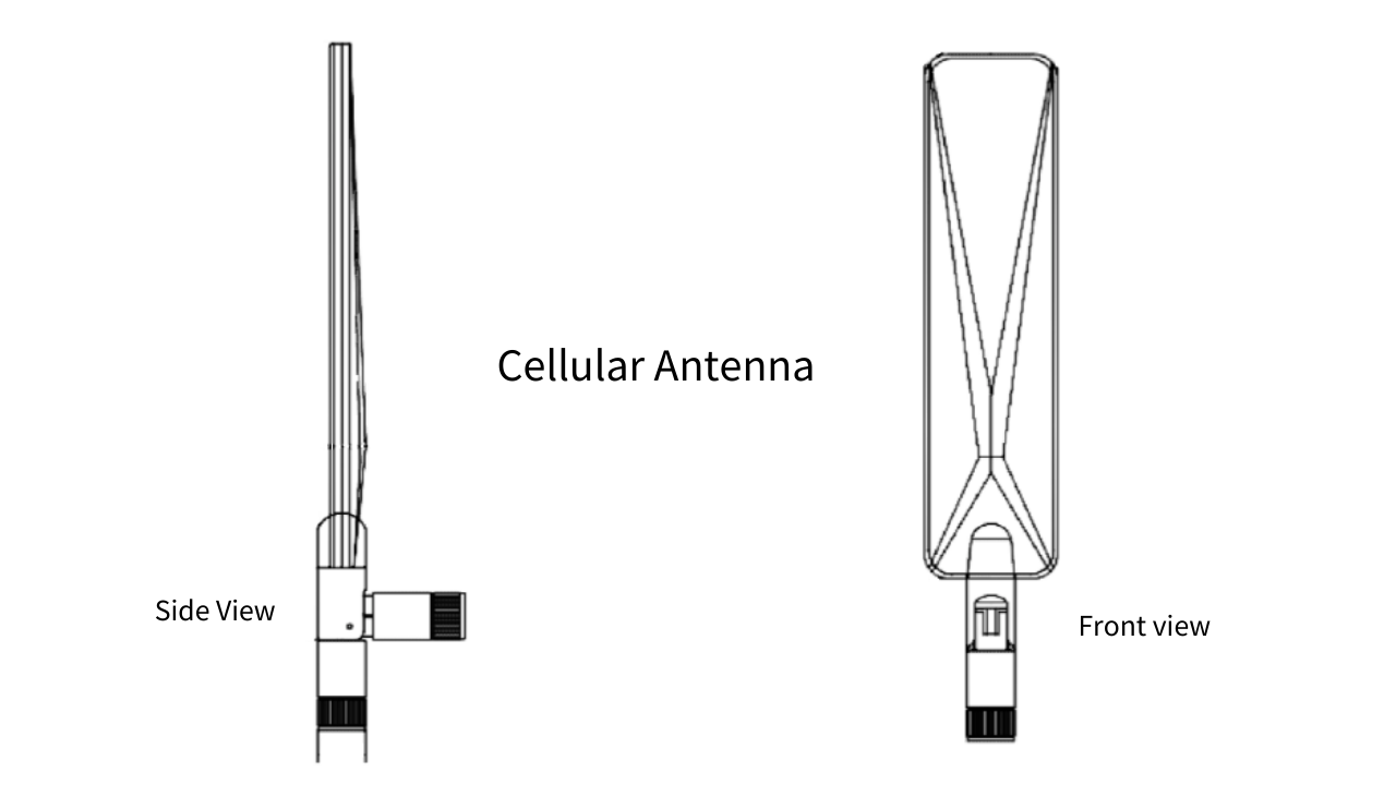
3. Antenna
The Cascade-500-W comes with two antennas for cellular connectivity. Each antenna should be mounted in a vertical orientation and angled away from metal for optimal signal.
Installation
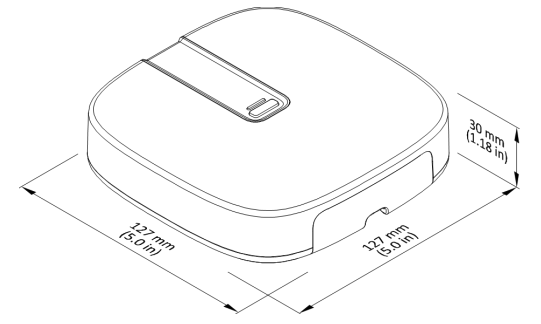
Cascade-500 Gateway Dimensions
Before the gateway is permanently installed, look at the back (mount side) and record the unit Serial (1) or scan the 2D barcode (2), as shown below.
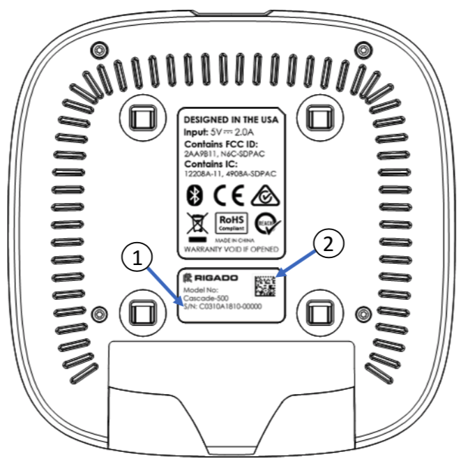
Back of a Cascade-500 Gateway
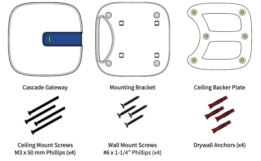
Mounting Equipment
A mounting kit is an available accessory for each Cascade-500 IoT Gateway. The mounting kit includes:
1 x Cascade Gateway
• 2 x Cellular Antennas (Cascade-500-W and Cascade-500-X only)
• 1 x Power supply with international adapters (optional)
• 1 x Wall/Ceiling Mount Kit:
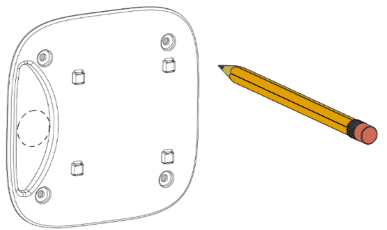
o 1 x Cascade mounting bracket
o 1 x Cascade ceiling backer plate
o 4 x M3 x 50 mm Length, Pan Head, Phillips #1, Machine Screw
o 4 x Screw, Pan Head Phillips Sheet Metal #6/18x1.25"
o 4 x Drywall Anchor, #6 Screw, 1-1/4" Length
Mounting Tools
To use the Wall/Ceiling Mount kit provided, the following tools are required (not included):
- Phillips screwdriver
- Drill and drill bit - 3/16" for wall, or 1/8" (3-4 mm) for ceiling mounting
- Drywall saw or keyhole saw for 1" cable pass-through hole
Mounting Instructions
Rigado recommends mounting the Gateway on a wall or ceiling, at least 6ft (2m) off the ground. If mounting on a wall, position the unit so that the connectors (USB, Ethernet, etc.) are facing down. This will ensure the mounting bracket attachment mechanism is secure against incidental removal.
Use the mounting bracket as a template to mark the hole locations on the wall or ceiling.
If mounting to the wall, use a 3/16" (5 mm) drill bit. If mounting to a ceiling tile, use a 1/8" (3-4 mm) drill bit.
If a hole is needed for any cables, also mark this in the appropriate cable opening space in the mounting bracket.
Attach the mounting bracket to the surface using the appropriate method:
Wall Mounting
Push the provided drywall anchors into the drilled holes, then place the mounting bracket snugly against the wall. Using a screwdriver, screw the wall mount screws into the drywall anchors.
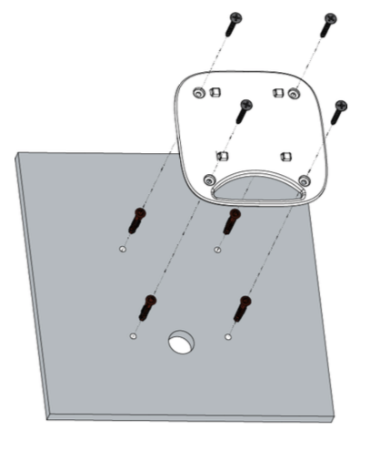
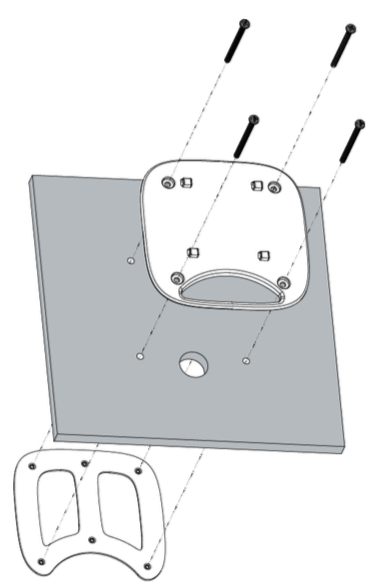
Ceiling Mounting
Place one ceiling mount screw through one of the mounting brackets screw holes, and push through the corresponding drilled ceiling hole. Use this screw to guide placement of the ceiling backer plate to the opposite side, then use the screwdriver to screw in this and the remaining ceiling mount screws.
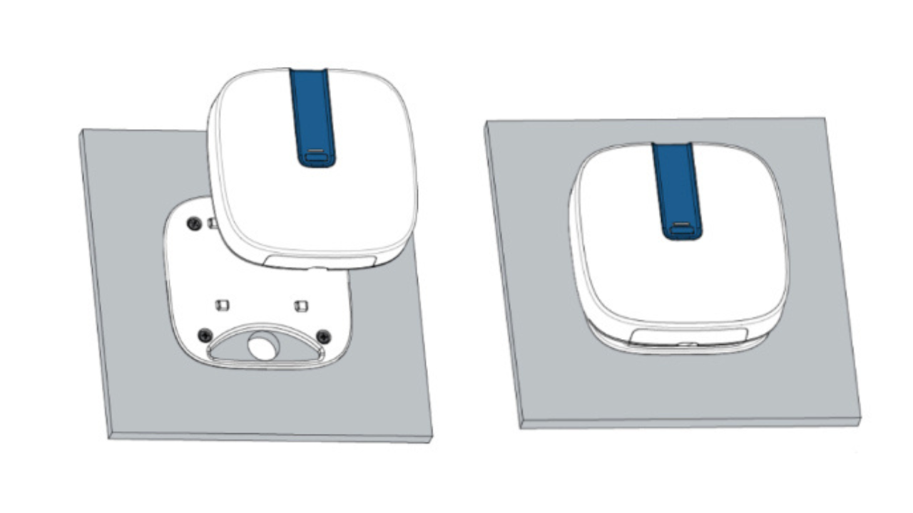
Once the mounting bracket is installed, line up the four hooks of the mounting bracket with the corresponding holes on the back of the gateway and press the two together. To lock in place, slide the gateway down towards the cabling hole until it clicks into place.
Drilling Hole Template and more information available inside our complete PDF Installation Guide. Download here.
Mounting Alternatives
The ceiling mount kit can be used to mount the gateway around a bar or beam. Large metal surfaces can interrupt or degrade signal strength for BLE, Wi-Fi, or cellular. Installing a gateway on a metal beam should be done only when the gateway has line-of-sight to the sensors and devices it connects to.
Updated 11 months ago